Donnerstag, 18. Juni 2015

Amateure und Profis

Es gibt Funkamateure die mehr vom Fach verstehen als ihre Freunde vom professionellen Sektor - und umgekehrt.

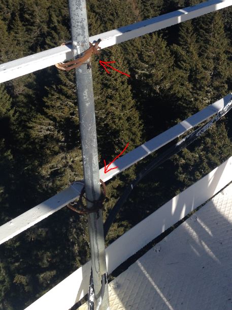
Hier ein Schnappschuss von einer Antennenmontage für die Bergrettung in einer Ausführung wie man's NICHT machen soll:


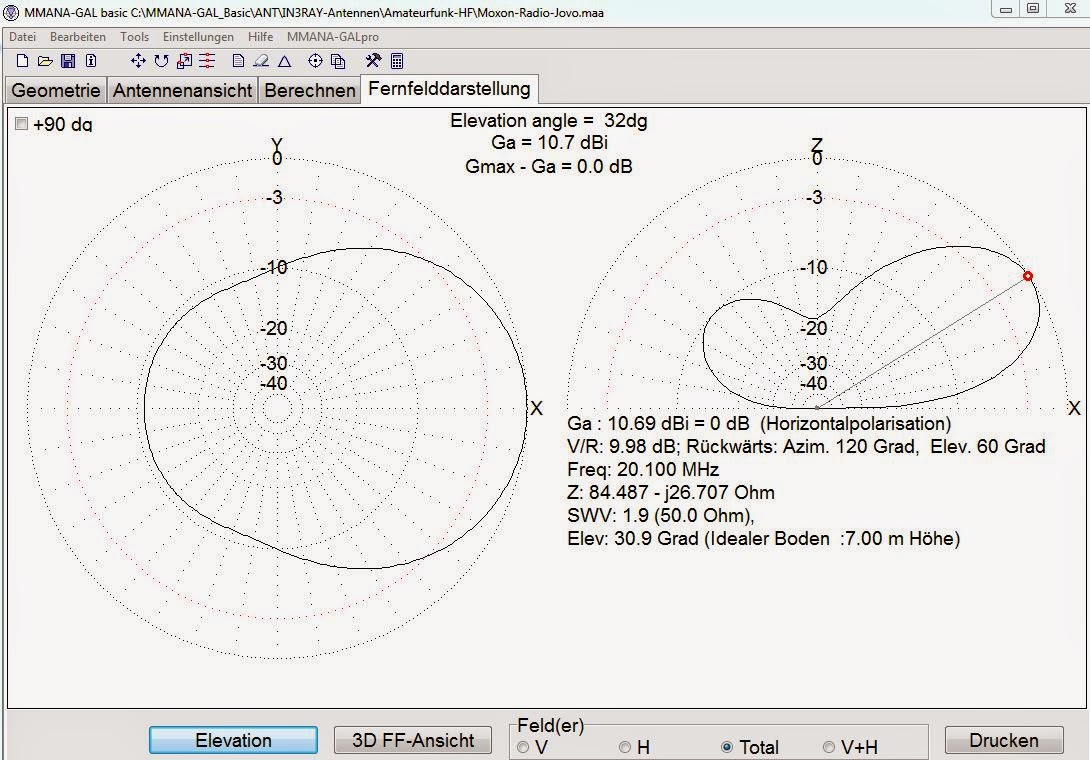
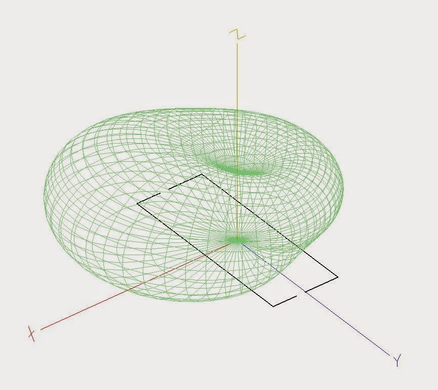
Jede Antenne braucht in Abhängigkeit ihres Typs und der Wellenlänge einen gewissen minimalen freien Raum um sich, damit sich das Antennendiagramm so ausbilden kann wie berechnet. Werden diese Abstände nicht beachtet und die Antennen zu nahe an störenden Objekten montiert (Mauern, Blechen, Eisentraversen, andere Antennen, etc.), wird das Antennendiagramm "verzogen" und stimmt nicht mehr mit den Katalogdaten überein. Es bilden sich Gewinnmaxima und Nullstellen aus die kaum erahnt werden können.
Hier noch zwei weitere "schräge" Beispiele wie man's NICHT machen soll:


Mittwoch, 8. April 2015

Radio Jove goes SDR

Nowadays "Software Defined Radios" are the state of technology. They are cheap and you can do a lot of things with them.

With a "DVB-T" Receiver that includes a "RTL2832U" - chip combined with the wonderful freeware program "SDR-Sharp" you will own a multimode receiver for a frequency range of about 60 - 1200 MHz (!) with excellent properties.

Shortwave signals must be converted in a higher frequency for reception with the DVB-T - USB Receiver. Such a converter usualy uses the mixer-frequency of 100 MHz. For example: if you receive a signal of 15 MHz (+100 MHz), you will find the signal on your receiver-stick on 115 MHz.


The only disadvantage of the receiver is its poor selectivity of the incoming antenna signal. Therefore I recommend the use of a Bandpass Filter for the frequency range of interest.
The RF2080 C/F Calibrated Noise Source and Bandpass Filter offered by the RADIO JOVE Project will do a great job. It has the additional advantage of a calibrated noise source wich allows you to create defined reference levels.

Let's look at the most important settings:


Turn the AGC off!


After setting the receiver at work properly, connect the audio-output using a (virtual) cable with the input of the great "Radio SkyPipe" - programm:


At least connect the input of the Up-Converter with an appropriate antenna.

An MOXON - antenna for the RADIO JOVE - NASA Project

The Radio JOVE project is a hands-on inquiry-based educational project that allows students, teachers and the general public to learn about radio astronomy by building their own radio telescope from an inexpensive kit and/or using remote radio telescopes through the internet. Participants also collaborate with each other through interactions and sharing of data on the network.

( = citation from the official "Radio Jove"-website: http://radiojove.gsfc.nasa.gov/index.html )

The advantage of the "Moxon"-antenna in comparison with the double-dipole-antenna in the description on the Websites of "Radio Jove" consists in its smaller size and only one feed cable instead of two feed-cables and one power splitter. The antenna pattern is almost the same.

The antenna is calculated for the centerfrequency of 20,1 MHz.

On the web you can find more than one calculator for "MOXON" - antennas.
I calculated with the following one: w4.vp9kf.com/moxon_design.htm


The data was obtained from the "MMANA-Gal" - Antenna Simulation Programm for a hight of 7 meters (= 23 feet):


Donnerstag, 26. Februar 2015

1:1 Balun KW + 6m ohne Ringkern

Der große Vorteil von Drahtgewickelten Baluns besteht darin, dass kein Ringkern nötig ist. Ringkerne sind eine wunderbare Sache, aber sie liegen oft bunt in der Bastelkiste rum und es ist mühsam heraus zu finden welchen AL-Wert der Ringkern hat und für welche Frequenz und welche Leistung der jeweilige Kern taugt.
Für ordentliche Naturen gestaltet sich das natürlich leichter.
Trotzdem: Drahtgewickelte Balun's haben den Vorteil, dass die Problematiken die Ringkerne mit sich bringen können einfach wegfallen.

Hier ein Bauvorschlag für einen 1:1-Balun:


3 X 16 cm Kupferlackdraht zwischen zwei Zangen kräftig verdrillen. Dann die Enden entsprechend des allgemein bekannten Wickelschemas (S. z.B. Rothammel-Antennenbuch) verlöten. Fertig!


Ich habe um eine bessere mechanische Stabilität zu erreichen den verdrillten Kupferlackdraht um ein PVC-Installationsrohr mit 16 mm Durchmesser gewickelt.


Die Messwerte lassen keinen Wunsch offen:


Dietrich Drahtlos:
Das Ziel muss sein:
billig, einfach und klein.  

Dienstag, 27. Januar 2015

Empfangssignal - Splitter

Möchte man mehrere Empfänger gleichzeitig an einer Antenne betreiben kann das Emfangssignal mit Hilfe eines einfachen Widerstandnetzwerkes aufgeteilt werden. Im Büchlein "Praxis der Fernsehantennen Teil2" von Karl Rothammel findet sich eine Tolle Beschreibung dafür. Die Formel zur Berechnung:


Wobei: R=Widerstandswert in Ohm
             Z=Wellenwiderstand der Antennenleitung (z.B. 50 Ohm)
             n= Anzahl der Ableitungen


Alle Widerstandswerte sind gleich groß. Für 50 Ohm und drei Ableitungen ergeben sich 25 Ohm für die vier Widerstände. Annähernde Werte eignen sich bedenkenlos.


Ich benutze diesen Splitter für den LMK + UKW-Empfang. Bei einem Splitter mit drei Abgängen wird das Signal um ca. 10 dB gedämpft.